TM 1-1520-240-10
6-6-5
on the floor formers. The floor limits are the
same as the concentrated load limits in the
treadway and center section of the floor, that
is 2,500 pounds and 1,000 pounds.
6-6-13. Compartment Identification.
The cargo compartment is divided, for weight and bal-
ance purposes, into three compartments designated
C,D, and E, running fore and aft. (fig. 6-6-1). When the
cargo ramp is used as an extension of the cargo compart-
ment, it is designated as F for weight and balance purpo-
ses. These compartment designations and their limiting
fuselage stations are stenciled on the cargo compart-
ment walls.
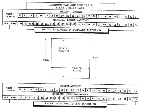
Figure 6-6-2. Maximum Package Size (Sheet 2 of 3)
6-6-14. Compartment Capacities.
Based on a maximum distributed floor loading of 300 psf,
the compartment capacities can be obtained by multiply-
ing the floor loading by the floor area of the individual
compartment; however, this weight may exceed present
limitations. Figure 6-6-4 lists the maximum capacity of
each compartment. In addition to the limitations in figure
6-6-4, compartment loads will be limited by those limita-
tions set forth in Chapter 5.
6-6-15. Tiedown Fittings.
Tiedown fittings (fig. 6-6-3) for securing cargo are
installed on the cargo compartment floor and on the ramp
floor. All the fittings are D-ring types. There are 87
5,000-pound-capacity tiedown rings (83 in the fuselage
floor and 4 in the ramp floor) and eight 10,000-pound-ca-
pacity tiedown fittings. The fittings are normally used with
tiedown devices which will not exceed the limits of the
fitting.
6-6-16. Five Thousand-Pound Capacity Tiedown Fit-
tings.
The 83 5,000-pound-capacity tiedown fittings in the car-
go compartment floor are equally spaced in five rows
spaced 20 inches apart longitudinally. The four in the
ramp are in a rectangular pattern. Each 5,000-pound-ca-
pacity fitting swivels freely and is capable of resisting a
single maximum load of 5,000 pounds exerted along any
radius of a hemisphere, the flat side of which is the sur-


