TM 1-1520-240-10
3-2-11
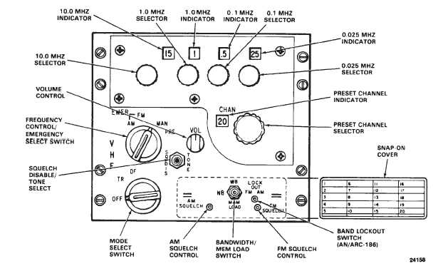
Figure 3-2-5. VHF AM/FM Radio Set (AN/ARC-186)
b. Transmit-receiver mode.
(1)
Mode select switch — TR.
(2)
Frequency
Control/Emergency
Select
Switch — As required. If greater receiver sensitivity is
required, set the SQ DIS/TONE switch to SQ DIS.
(3)
VOL control — As required.
c. Stopping. Mode select switch — OFF.
d. Presetting channels. Perform the following steps
to preset a channel to a desired frequency.
(1)
Mode select switch — TR.
(2)
Frequency select switch — MAN.
(3)
Rotate the four frequency select switches
until the desired frequency is displayed.
(4)
Rotate the preset channel selector until the
desired channel appears in the preset CHAN indicator.
(5)
Remove the snap-on cover.
(6)
Momentarily set the bandwidth WB, NB,
MEM LOAD switch to MEM LOAD. The preset frequency
is now in memory.
(7)
Using a soft lead pencil, record the loaded
frequency opposite the channel number on the snap-on
cover.
(8)
Using the above procedure, preset any oth-
er channels and install the snap-on cover.
3-2-16. VHF/FM Radio Set (AN/ARC-201).
The AN/ARC-201 is located on the pilot instrument panel
and provides two-way frequency modulated (FM narrow
band voice communications.
a. The following items from the airborne radio sys-
tem.
ITEM
DESCRIPTION
1.
Receiver-Transmitter Radio Panel Mounted
(RT-1476)
2.
Amplifier (AM 7189)
b. Essential Operational Technical Characteristics.
Except where specifically indicated otherwise, the follow-
ing operational/technical parameters are the minimum
essential characteristics. Unless otherwise specified,
they apply to each radio configuration.


