TM 1-1520-240-10
4-1-14
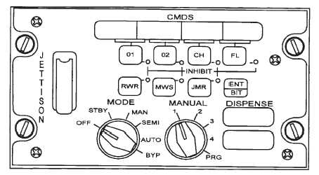
Figure 4-1-7. AN/ALE-47 Countermeasures Dispenser System (CMDS)
4-1-19. The AN/ALE-47 Programmer.
The AN/ALE-47 programmer, located at STA 355 in the
left side of the cabin, is the central processing unit for the
CMDS and provides the interface between the DCDU
and the four flare dispensers via two sequencers. The
programmer receives input data from the AN/ALQ-156
missile detection system, processes it to determine the
appropriate dispense response, and sends fire com-
mands to the sequencers when CMDS is in Auto or Semi
Auto mode of operation.
The software program within the programmer that man-
ages all communications, operations, and calculations is
called the Operational Flight Program (OFP). The pro-
grammer also contains the Mission Data File (MDF)
which is user-programmable and contains data elements
that enable the CMDS to be configured to specific pay-
load types, dispense sequence, and dispense quantities.
The OFP and MDF are loaded into the programmer using
Mission Load Verifier (MLV) via the MLV interface port
located in the cabin at station 359 overhead.
4-1-20. AN/ALE-47 Sequencers.
There are two AN/ALE-47 sequencers installed in the aft
cabin at station 547 buttline (BL)40L and station 543
BL40R. The sequencers receive payload type and fire
commands from the programmer over the Sequencer
Data Link (SDL). The sequencers select the dispenser
with the appropriate payload and send high power im-
pulses to the dispenser(s) and magazine to dispense the
programmed expendable. The sequencers also detect
magazine type, monitor the remaining inventories in the
magazines, and detect payload misfires. This informa-
tion is sent to the programmer via the SDL. Each se-
quencer also performs internal BIT. Sequencer NO. 1
controls the two dispensers (1 and 3) on the LH side of
the aircraft, and sequencer NO. 2 controls two dispens-
ers (2 and 4) on the RH side of the aircraft.
4-1-21. AN/ALE-47 Safety Switch.
A safety switch located at station 518 BL50L is installed
in the CMDS to provide a safeguard against inadvertent
dispensing of expendable. When the safety pin is
installed in the safety switch, squib power (28 Vdc) to the
sequencers is interrupted, inhibiting dispensing expen-
dables. The safety switch provides ground to the AN/
ALE-47 squib power relay (located in the AN/ALE-47
junction box at station 410 BL22.5L) when safety pin is
removed allowing squib power to the sequencers for dis-
pensing expendables.
4-1-22. Dispenser Assemblies.
Four flare dispenser assemblies are mounted in pairs on
the LH and RH sides of the aft fuselage. Each dispenser
assembly consists of a housing and a breech plate. The
breech plate provides interface for the payload module
and routes firing and polling pulses from the sequencers
to the payload squibs.
4-1-23. Payload Module Assemblies.
The payload module assemblies are mounted on the
dispenser assemblies. Each payload module assembly
consists of a payload module (magazine), and an EMI
(HERO) gasket/breech plate. The payload modules can
hold up to 30 expendable cartridges which are loaded
and installed in the dispenser assemblies prior to the
mission.
The payload modules are capable of being loaded with
3 types of expendables; XM211, XM212 and M206. They
use either the M796 or BBU-35/B cartridge.