TM 1-1520-240-BD
9-2.
DAMAGE ASSESSMENT PROCEDURES.
a.
Wire Identification. The most difficult and
time consuming part of electrical and avionics battle
damage assessment is wire identification. Added and
repaired
wiring
should
be
identified
to
aid
in
troubleshooting. If time permits, tape or sleeving at
each end of added pieces, may be used. Use a material
suitable for the ambient temperature range. Typical
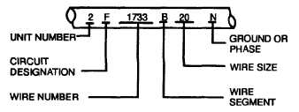
wire and circuit identification schemes are shown in
Figure 9-2.
Figure 9-2. Circuit Identification
b.
Circuits Identification. The unit number and
circuit designation letter identify the type of circuits. The
wire
number consists of one or more digits. It is used to
distinguish between wires in the same circuit. The wire
segment letter is used to distinguish between conductor
segments (a wire segment between two terminals or
connections). The wire size number is used to identify
the AN or AL or the wire or cable. The ground, phase,
or thermocouple letter(s) are used as suffixes to the wire
identification code to further identify certain wires.
Ground wires are identified with an N suffix. Phase
letters A, B, or C are added to identify the phase of
wires that are in the three-phase wiring of alternating
current (AC) systems. For thermocouple wire, the
following suffixes are added to the identification code:
AL (Alumel), CR (Chromel), FE (Iron), CN (Constantan),
and CU (Copper).
9-3.
DEFERMENT.
Repair
of
systems
and
subsystems
which
are
not
critical
to
mission
accomplishment, may be deferred if safety of flight is
not significantly degraded. Requirements must be
examined to determine if relaxed standards for repair
and aircraft performance can be accepted. The
commander may defer combat maintenance and battle-
damaged repair, even if doing so places operational
limitations on the aircraft.
SECTION III. BATTLE-DAMAGE REPAIRS
9-4.
INTRODUCTION . The objective of electrical and
avionics system battle-damaged repair is to restore
damaged circuits which are essential. It is also used to
make nonessential circuits safe. The repair procedures
in this section are designed to quickly return an aircraft
to a flyable condition.
9-5.
ELECTRCTRICAL AND AVIONICS REPAIRS .
Electrical and avionics equipment receiving significant
battle damage will usually not be repairable. The
equipment may require replacements for nonessential
system units are not available, the technician should,
when
possible,
make
the
necessary
repairs
or
adjustments on the unit for one more combat sortie.
However, avionics wiring, coaxial cables, and general
aircraft wiring can be repaired using a variety of
procedures and materials. Most of them are considered
standard for temporary repairs.
9-6.
ISOLATION OF NONESSFNTIAI SYSTEMS . To
isolate damaged nonessential system wiring, crimp-on
end caps, tape or any other insulating method may be
used. Secure wires to some form of structure.
9-7.
THE ACM/BDR WIRING REPAIR SET . The
wiring repair set contains the necessary tools, materials,
and test equipment for the repair of all combat damaged
U.S. Army rotary-wing aircraft electrical wiring systems.
Paragraph 9-7.a. describes the wiring repair set, and
paragraph 9-7.b. contains general instructions for using
its four major subassemblies.
a.
Description. The wiring repair set consists of
four major subassemblies (kits). The kits are packaged
in militarized fiberglass cases and are transportable by
one
or
more
maintenance
personnel.
Each
subassembly kit contains the necessary tools, materials,
and test equipment to perform a specific portion of the
aircraft wire repair task. Three kits are dedicated for use
at the AVIM or AVUM areas as follows:
9-2


