TM 1-1520-240-BD
•
Bundle forming and protection.
•
Circular and flat connector repair.
•
Terminal board replacement.
•
Terminal lug installation.
Prior to performing any of the listed repairs, the repair
technician must be knowledgeable in the application of
the basic repair procedures, and proficient in the use of
wiring repair tools and materials. The techniques
illustrated, when applicable, duplicate the "short-form"
instruction for each repair material that are affixed to the
storage box cover.
(1)
Unshielded Primary Wire Splicing. The
repair set provides wire splice capability for all 24 to 12
AWG wiring used on Army helicopters, regardless of the
wire temperature ratings. Splices are provided for wires
rated at 1050C or below (wires identified as M5086,
MS26313, M7078/3, 5, 7, and M27500 A, B, C, P, AA,
AB, or AD); TM 1-1520-240-BD and for wires rated at
125° C or above (wire identified as M22759/16, 18, 32,
34, 43 and M81381/7, 11). All primary wire stocked in
the repair set is M22759/43, rated at 200°C. This wire
may be spliced to any existing aircraft wiring provided
that the splice selected is appropriate for the existing
aircraft wiring temperature rating. Wire bundle repairs
should be accomplished using the splicing techniques
described in this section. Care should be exercised to
stagger splices. Where possible, splices in adjacent
wires in a bundle should be separated by at least one
splice length. This may require the use of the pre-made
splice segments (Figure 9-10) or locally manufactured
jumper wires made from the kit primary wire stock
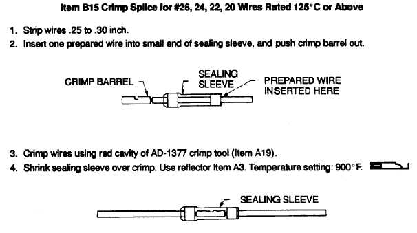
spliced into the existing aircraft wiring. Figures 9-4, 9-5,
and 9-6 illustrate the technique for the splicing of 125°C
or above rated wires of the sizes indicated. Figures 9-7,
9-8, and 9-9 illustrate the technique for splicing wires
rated at 105oC or below for the wire size indicated.
Figure 9-10 illustrates the use of the premade wire
repair segments on primary wires rated at 125°C or
above. Adherence to these techniques results in a
permanent, environmentally sealed primary wire splice.
Figure 9-4. Item B15 Crimp Splice
9-9


