TM 55-1520-240-T
6-2.3
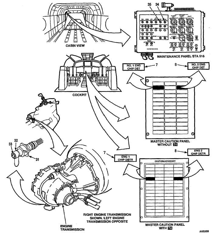
TRANSMISSION CHIP DETECTORS AND DEBRIS SCREENS OPERATIONAL CHECK (Continued)
6-2.3
TASK
RESULT
46.
Remove right engine transmission chip detector plug
(31) and inspect it. (Refer to TM 55-1520-240-23.)
47.
Connect connector to plug (31).
48.
Place a jumper wire between chip detector body (32)
NO. 2 ENG CHIP DET (Without 74 ) ENG 2 CHIP DETR
and chip detector ring (33).
(With 74 capsule (8) shall come on. RIGHT TRANS-
MISSION CHIP DETECTOR indicator (34) shall change
to black-and-white fan. If capsule (8) is not on or indicator
(34) is still black, go to Task 6-2.20.
49.
Remove jumper wire. Install right engine transmis-
NO. 2 ENG CHIP DET (Without 74 )ENG 2 CHIP DETR
sion chip detector plug (31).
(With 74 ) capsule (8) shall go out.
50.
Remove left engine transmission chip detector plug
(31) and inspect it. (Refer to TM 55-1520-240-23.)
51.
Connect connector to plug (31).
52.
Place a jumper wire between chip detector body (32)
NO. 1 ENG CHIP DET (Without 74 )ENG 1 CHIP DETR
and chip detector ring (33).
(With 74 ) capsule (7) shall come on. LEFT TRANSMIS-
SION CHIP DETECTOR indicator (35) shall change to
black-and-white fan. If capsule (7) is not on or indicator
(35) is still black, go to Task 6-2.21.
53.
Remove jumper wire. Install left engine transmission
NO. 1 ENG CHIP DET (Without 74 ) ENG 1 CHIP DETR
chip detector plug (31).
(With 74 capsule (7) shall go out.
54.
Set GND switch (6) to RESET, then to GND.
Indicators (29, 30, 34, and 35) shall change to all-black.
GO TO NEXT PAGE
Change 17 6-39