TM 55-1520-240-T
6-2.3 TRANSMISSION' CHIP DETECTORS AND DEBRIS SCREENS OPERATIONAL CHECK (Continued)
6-2.3
TASK
RESULT
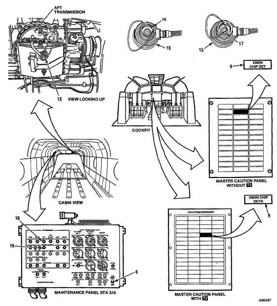
CHECK AFT TRANSMISSION CHIP DETECTOR AND DEBRIS SCREEN INSTALLATION
15. Disconnect connector from debris detection screen
cap (15).
NOTE
Cap holds 2 to 3 ounces of oil.
16. Hold container under cap (15). Push up center of cap
and pull down on cap edge to remove cap. Drain oil
into container.
17. Filter drained oil through cloth (E104). Check cloth,
screen (16), and chip detector (17) for debris. Retain
debris for contamination analysis. (Refer to TM 55-1520-
240-23.)
18. Connect connector to cap (15).
CAUTION
Be careful when placing jumper wire on screen.
Rough handling could damage debris screen.
19. Place a jumper wire across at least four consecutive
AFT TRANSMISSION DEBRIS SCREEN indicator (19)
wires on the inside mesh of screen (16).
shall change to black-and-white fan. If it does not, go to
Task 6-2.13.
20. Remove jumper wire from debris screen. Place
XMSN CHIP DET (Without 74) 3 XMSN CHIP DETR
(With 74)
jumper wire across gap of chip detector (17).
capsule (9) shall come on. FWD TRANSMISSION
CHIP DETECTOR indicator (18) shall change to black-
and-white fan. If capsule (9) does not come on or indicator
(18) does not change display, go to Task 6-2.14.
21. Remove jumper wire .
XMSN CHIP DET (Without 74) 3 XMSN CHIP DETR
(With 74) us capsule (9) shall go out.
22. Set GND switch (6) to RESET, then to GND.
Indicators (18 and 19) shall change to all-black.
23. Install debris detection screen cap (15).
GO TO NEXT PAGE
6-34 Change 17 Page 6-35 is a blank page.