TM 55-1520-240-T
6-2.3
TRANSMISSION CHIP DETECTORS AND DEBRIS SCREENS OPERATIONAL CHECK (continued)
6-2.3
TASK
RESULT
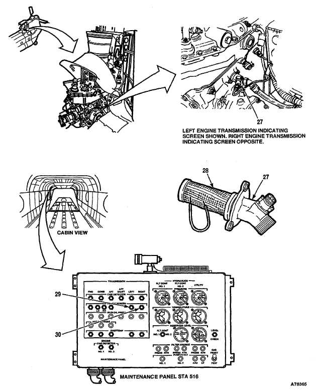
CHECK ENGINE TRANSMISSION CHIP DETECTOR AND DEBRIS SCREEN INSTALLATION
38.
Remove left engine transmission debris detection
screen (27) and inspect it. (Refer to TM 55-1520-240-23.)
39.
Connect connector to engine transmission debris
detection screen (27).
CAUTION
Be careful when placing jumper wire on screen. Rough handling could damage debris screen.
40.
Place a jumper wire across at least four consecutive
LEFT TRANSMISSION DEBRIS SCREEN indicator (29)
wires on the outside mesh of screen (28).
shall change to black-and-white fan. If it does not, go to
Task 6-2.18.
41.
Remove jumper wire. Install left engine transmission
debris detection screen (27). (Refer to TM 55-1520-240-23.)
42.
Remove right engine transmission debris detection
screen (27) and inspect it. (Refer to TM 55-1520-240-23.)
43.
Connect connector to engine transmission debris
detection screen (27).
CAUTION
Be careful when placing jumper wire on screen. Rough handling could damage debris screen.
44.
Place a jumper wire across at least four consecutive
RIGHT TRANSMISSION DEBRIS SCREEN indicator (30)
wires on the outside mesh of screen (28).
shall change to black-and-white fan. If it does not, go to
Task 6-2.19.
45.
Remove jumper wire. Install right engine transmis-
sion debris detection screen (27).
(Refer to TM 55-1520-240-23.)
GO TO NEXT PAGE
6-38 Change 17