TM 1-1520-240-10
4-1-7
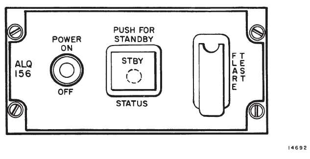
4-1-6. Controls and Indicators, Missile Detector Set
(AN/ALQ-156). (fig. 4-1-5)
CONTROLS /
INDICATOR
FUNCTION
POWER OFF/ON
At ON, power is applied to
set. The switch is locked at
ON. Signals radiate after the
normal warmup period is
completed.
STBY Indicator Light
on STATUS Switch
Lights when switch is de-
pressed and system is in
standby operation.
Amber Warmup Cau-
tion Light on STATUS
Switch
Lights when power is ap-
plied to set and remains on
until operating temperatures
are reached.
FLARE TEST Switch
Simulates launch command
signal to flare dispenser.
CM INOP Caution
Light (on caution pan-
el)
When lit indicates the set
has failed and the helicopter
is without countermeasures
protection.
CM JAM Caution
Light (on caution pan-
el)
Lights when system detects
mutual interference from
nearby countermeasures
sets or enemy jamming.
4-1-7. Normal Operation; Countermeasure Set.
WARNING
An accidental flare launch can occur when
Flare Dispenser System is armed (control
switch at ARM) and the Countermeasure
Set is operating (CM caution and indicat-
ing lights off). A flare launch will also oc-
cur is the FLARE TEST switch on the
countermeasures control panel is opera-
ted. Arm these systems only in cases
where a launched flare will not cause inju-
ry or property damage.
WARNING
During operation, the AN/ALQ-156 anten-
nas radiate radio-frequency energy. This
energy may cause burns to personnel
near the antennas. Be sure ground per-
sonnel are at least 6 feet from the anten-
nas when the control switch is at ON.
a.
Starting.
(1)
MSL DET SYS circuit breakers on No. 2
PDP — Check in.
Figure 4-1-5. Countermeasures Set Control Panel (AN/ALQ-156)