TM 1-1520-240-10
4-1-5
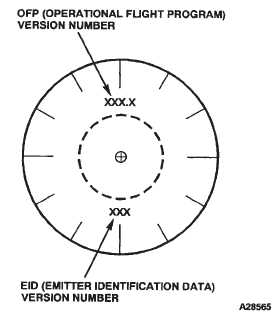
4-1-3). Check OFP and EID numbers are correct for the-
ater or mission.
Performs the Receiver and AN/AVR-2 status display.
See figure 4-1-4 for normal indicator displays, and faulty
indicator displays.
Performs a test on the synthetic voice status messages.
A no fault detected during test will end with message
APR-39 OPERATIONAL” any fault detected will end with
message “APR-39 FAILURE”, which will be heard over
the ICS.
Performs the plus (+) symbol display status. The plus (+)
symbol will be displayed, centered within the small circle
on the indicator, anytime the symbol is operational.
Figure 4-1-3. Radar Signal Detecting Set (OFP and
EID VERSION DISPLAY)
(c)
MODE switch — MODE 2 (down),
(d)
TEST switch — Press.
Performs the synthetic voice short count. Listen to syn-
thetic voice message and adjust volume. Mode 2 short
count is: “SELF-TEST SET VOLUME 5, 4, 3, 2, 1”.
(2)
The following fault display conditions are on
the result of a bad self test and will result in an audio
message “APR-39 FAILURE” over the ICS.
(a)
If a receiver fault is noted, faulty receiver
is shown as two triangles, (fig. 4-1-4) representing right
and left video channel (s) will be flashing.
(b)
A faulty C/D band amplifier in a proces-
sor is shown as a flashing square centered on indicator
display ( fig. 4-1-4).
(c)
The Laser Detecting Set (LDS)(AN/
AVR-2) status is displayed along with the receiver status.
A faulty LDS quadrant is shown as a flashing asterisk.
LDS faults do not cause an audio message “APR-39
FAILURE”, heard over the ICS.
(d)
If LDS is not installed, all four quadrants
(asterisks) will flash.
(3)
Operating In A Dense Signal Environment.
(a)
When a dense signal environment is de-
tected, the plus (+) symbol on the Radar Signal Detecting
Set (RSDS) indicator will flash, and the voice message
“THREAT DETECTION DEGRADED” will be announced
over the ICS.
(b)
Position mode switch to mode 2 (terse
mode). When the plus(+) symbol stops flashing, the
voice message “THREAT DETECTION RESTORED”
will be announced over the ICS.
4-1-5. Countermeasure Set (AN/ALQ-156).
The Countermeasures Set (AN/ALQ-156) detects the
approach of anti-aircraft missiles, and signals the M-130
Flare Dispenser to launch flares to decoy the missiles
from the helicopter. The set consists of a control unit on
the console, a receiver-transmitter in the electronics
compartment, two antennas on the bottom of the fuse-
lage, and two caution light capsules on the master cau-
tion panel. The set alternately applies pulsed signals to
the two antennas which radiate the signals about the
helicopter. A missile approach is detected by the fre-
quency shift of the transmitted signals echo returned
from the missile. Any echo is received during the interval
following each pulsed transmission. Built-in-test-equip-
ment monitors system operation. If a malfunction is de-
tected, the system is disabled and the CM INOP caution
capsule on the master caution panel will come on. Also,
if enemy jamming or interference from other counter-
measures sets is detected, the set will automatically shift
to a clear channel. The set receives AC electrical power
from the No. 2 AC bus through the MSL DET SYS circuit
breaker on the No. 2 PDP. The set receives DC power
from the No. 2 DC bus through the MSL DET SYS circuit
breaker also on the No. 2 PDP.