TM 1-1520-240-10
4-1-4
NOTE
The concentric circle is a reference mark only
and is not a range marking.
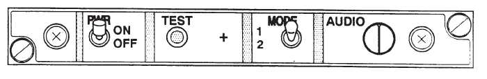
4-1-3. Controls and Function, Radar Signal Detect-
ing Control.
CONTROLS/
INDICATOR
FUNCTION
PWR Switch
Two position switch. At ON,
power is applied to set. Set
is operational after 1-minute
warmup.
TEST Switch
Switch is spring-loaded to
off. When pressed, the self
test function is enabled.
CONTROLS/
INDICATOR
FUNCTION
MODE Switch
Two position switch. Selects
synthetic voice message for-
mat. Mode 1 (up) selects
normal message format.
Mode 2 (down) selects terse
(abbreviated) message for-
mat. Mode 2 reduces audio
distractions when operating
in dense signal environ-
ments.
AUDIO
When turned clockwise, the
audio output of the set is in-
creased.
Figure 4-1-2. Radar Signal Detecting Set Control
4-1-4. Normal Operation — Radar Signal Detecting
Set.
This paragraph provides radar signal detecting set oper-
ating procedures.
CAUTION
To prevent damage to the antenna detec-
tors (when operating) never operate the
AN/APR-39A(V)1within 60 yards of ground
based radars or within six yards of air-
borne radar antennas. Operating the sys-
tem closer than these limits may damage
the antenna detectors. Allow an extra mar-
gin for new, unusual, or high-powered ra-
dar transmitters.
CAUTION
Excessive indicator display brightness
may damage the CRT. Set indicator BRIL
control for readable display.
a.
Starting.
(1)
PWR switch — ON. Allow 1 minute for war-
mup – Check for synthetic voice message “APR-39
POWER UP”.
(2)
BRIL control — adjust display of (+) symbol
(3)
MODE switch — Select MODE 1 (up) for
normal messages. Select MODE 2 (down) for terse (ab-
breviated ) messages.
b.
Self-test check.
NOTE
SYSTEM SELF–TEST provides a four step
test of system functions. A complete system
self-test is initiated any time the test button is
pressed. The complete system self test runs
in less than 30 seconds. The following is a
description of the system functions.
(1)
TEST - As follows:
(a)
MODE switch — Set position 1 (up)
(b)
TEST switch — Press.
A synthetic voice long count is performed. The audio
message “SELF-TEST, SET VOLUME 1, 2, 3, 4, 5, 6, 7,
8, 9, 10, 11, 12” will be heard on the ICS.
A display of two numbers which represent the installed
software revision on the indicator; one number (OFP-Op-
erational Flight Program) at the top and one number
(EID-Emitter Identification Data) at the bottom (fig.