TM 1-1520-240-10
2-9-1
SECTION IX. UTILITY SYSTEMS
2-9-1. Anti Icing Systems.
Anti icing is provided for the pitot tubes, AFCS yaw ports,
and pilot and copilot windshields. The center windshield is
not anti-iced, it is only defog.
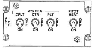
2-9-2. ANTI ICE Panel.
The ANTI ICE panel is located on the overhead switch
panel (fig. 2-9-1). It has three two-position W/S (wind-
shield) switches labeled CPLT, CTR, and PLT. The
switches positions are OFF and ON. In addition, a two-
position PITOT heat switch is in this panel. The switch
positions OFF and ON.
Power for the pilot and center windshields is from the No.
2 AC bus through the WSHLD ANTI ICE HEAT PILOT
and CTR circuit breakers. Power for the copilot wind-
shield is from the No. 1 AC bus through the WSHLD
COPLT HEAT circuit breaker on the No. 1 PDP. Anti-ice
control for the pilot and center windshield is from the
28-volt No. 2 DC bus through the WSHLD ANTI ICE
CONT CTR and PILOT circuit breakers on the No. 2 PDP.
Anti-ice control for the copilot windshield is from the
28-volt No. 1 DC bus through the WSHLD COPLT CONT
circuit breaker on the No. 1 PDP. Power to operate the
heater elements in the pitot tubes and yaw ports is sup-
plied by the No. 2 AC bus through the PITOT HEAT and
YAW PORT HEAT circuit breakers on the No. 2 PDP.
a.
W/S Switches. The pilot and copilot windshields
are anti-iced and defogged electrically. The center wind-
shield is defogged but not anti-iced. The laminated wind-
shield panels are heated electrically by current which
passes through a transparent conductive coating em-
bedded between the layers.
Figure 2-9-1. Anti Ice Panel
CAUTION
If windshield bubbling or delamination oc-
curs around the sensor element, immedi-
ately place switch to OFF for that wind-
shield.
When any switch is moved to ON, current flows to the
associated temperature controller and then to the wind-
shield. As the temperature of the windshield rises to a
preset value (about 44_), as sensed by the sensor ele-
ment, the electrical current to the windshield is inter-
rupted by the temperature control relay. Once the wind-
shield has cooled sufficiently, electrical current is
reapplied. This causes a cycling effect which maintains
windshield temperature within operating limits.
Operating temperature is on in less than 1 minute after
the switch is placed to on. When the switch is placed to
OFF, the anti-icing system is deenergized.
b.
PITOT Heat Switch. Heating elements prevent
ice accumulation in the pitot tubes and the yaw ports.
When the PITOT switch is placed to ON, power to the
heater elements in the pitot tubes and yaw ports is ap-
plied. When the switch is placed to OFF, the heating
elements are deenergized.
2-9-3. MAINTENANCE PANEL.
The MAINTENANCE PANEL is on the right side of the
cabin above the ramp (fig. 2-9-2). The panel is provided
to assist in the identification of system malfunction or
condition that may require servicing or other mainte-
nance. The panel is divided into four sections. They are
labeled TRANSMISSION, HYDRAULICS, ENGINE, and
GROUND CONTACT.
2-9-4. TRANSMISSION Section.
This section monitors the FWD, COMB, AFT, AFT
SHAFT, LEFT, and RIGHT transmissions. It consists of
six CHIP DETECTOR magnetic indicators, six DEBRIS
SCREEN a magnetic indicators, six MAIN OIL PRESS
indicating PRESS-TO-TEST lights, three AUX OIL
PRESS indicating PRESS-TO-TEST lights, and five
OVERTEMP magnetic indicators. Power to operate the
indicators is supplied by the No. 1 DC bus through the
HYDRAULIC MAINT PNL circuit breaker on the No. 1
PDP.
a.
CHIP DETECTOR Magnetic Indicators. When
the corresponding CHIP DETECTOR is bridged by fer-
rous particles, the associated chip detector indicator
changes from all-black to black-and-white. In addition,
the XMSN CHIP DET or ENG CHIP DET caution capsule
illuminates on the master caution panel.