TM 1-1520-240-10
2-9-2
LEFT
RIGHT
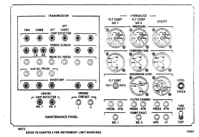
Figure 2-9-2. Maintenance Panel
b.
DEBRIS SCREEN Magnetic Indicators. There is
one indicator each for the FWD transmission, AFT trans-
mission, and the Left (No. 1) and Right (No. 2) engine
transmissions. There are two indicators for the COMB
transmission. one indicator for the left sump and one indi-
cator for the right sump.
NOTE
Their is no cockpit indication of a latched DE-
BRIS SCREEN magnetic indicator. If a DE-
BRIS SCREEN magnetic indicator latches,
the flight engineer shall advise the pilot imme-
diately.
The indicators are electrically connected to screens in
the sumps of each transmission. If the screen mesh is
bridged with conductive particles, the indicating circuit
closes and trips the corresponding DEBRIS SCREEN
magnetic indicator on the MAINTENANCE PANEL.
c.
MAIN OIL PRESS indicating Lights. If main oil
pressure drops below 20 psi in any transmission or 10
psi in the aft shaft bearing, the corresponding indicating
light will illuminate. in addition, the XMSN OIL PRESS
caution will illuminate on the master caution panel.
d.
AUX OIL PRESS indicating Lights. If auxiliary oil
pressure drops below 20 psi in the FWD or AFT trans-
mission or 10 psi in the COMB transmission, the corre-
sponding indicating light will illuminate. In addition, the
XMSN AUX OIL PRESS caution will illuminate on the
master caution panel.
e.
OVERTEMP Magnetic Indicators. Each OVER
TEMP magnetic indicator is electrically connected to a
temperature probe in the reservoir of each transmission.
If oil temperature in the transmission reservoir exceeds
140_C, a switch closes. When the switch closes, the
XMSN OIL HOT caution illuminates on the master cau-
tion panel and trips the corresponding OVERTEMP mag-
netic indicator on the MAINTENANCE PANEL, thus iden-
tifying the hot transmission.
2-9-5. HYDRAULICS Section.
This section monitors the FLT CONT NO 1, FLT CONT
NO 2, and UTILITY hydraulic systems. It consists of three
PRESSURE indicators, three fluid TEMPERATURE indi-
cators, two RESERVOIR LEVEL indicators, six FILTER
CHANGE indicating PRESS-TO-TEST lights, and four
PUMP FAULT indicating PRESS-TO-TEST lights. Power
to operate the indicators is supplied by the No. 2 DC bus


