TM 1-1520-240-10
2-11-1
SECTION XI. ELECTRICAL POWER SUPPLY AND DISTRIBUTION SYSTEMS
2-11-1. Electrical Power Supply System.
Alternating current (AC) is the primary source of power
to operate the electrical and electronic equipment. Three
AC generators, two driven by the aft transmission and
one driven by the APU, produce 115/200-volt 3-phase
400-Hz power. The system develops 28-volt DC through
two transformers rectifiers (RECT) one each in the for-
ward section of the left and right fuselage pods. DC is
also supplied by a 24-volt nickel-cadmium battery.
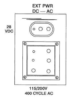
Both 115/200-volt 3-phase AC and 28-volt DC can be
supplied by operating the APU or by connecting an AC
external power source to the external power receptacles
(fig. 2-11-1). If the APU is running or AC external power
is connected, DC power is supplied by the helicopter
transformer rectifiers (RECT). If only DC external power
is supplied, AC power is not available on the helicopter.
Circuits are protected by circuit breakers (fig. FO-2 and
FO-5). The electrical load is divided between the two AC
generators (fig. FO-3 and FO-6). Should one generator
fail, the other will automatically take over the entire load.
When APU is running, its single generator powers the
entire load.
Figure 2-11-1. External Power Receptacles
2-11-2. AC System.
The AC system supplies 115/200-volt three-phase
400-Hz power from No. 1 AC generator to No. 1 three-
phase AC bus and from No. 2 AC generator to the No. 2
three-phase AC bus (fig. FO-3 and FO-6). The AC equip-
ment is powered by these buses. Some of the equipment
is operated by 115-volt single-phased AC and some
equipment by 26-volt AC power supplied through the
transformers.
The AC system is protected from overvoltage, undervol-
tage, and underfrequency conditions by generator con-
trol units. The generators will be disconnected from the
AC buses any time the RRPM drops below 82 to 85
percent for more than 3 to 7 seconds. The AC power
distribution system has four power sources, a contactor,
control circuit, an AC power transfer circuit, and two AC
buses.
The No. 1 and No. 2 generator power sources are two
main generators driven directly by the aft transmission.
The APU generators is driven directly by the APU. The
external power source is an AC power supply connected
to the helicopter.
No. 1 and No. 2 generators feed their respective buses.
If No. 1 and No. 2 generator fails (or are shut down), the
failed generator is isolated from its bus and the operating
generator feeds both buses. When No. 1 or No. 2 or both
generators are operating, APU generator and external
power are blocked from the AC buses.
When the APU generator is operating and the main gen-
erators are shut down (or rotors turning below about
84%) or switched off, the APU generator feeds both bu-
ses. When the APU generator is operating, external pow-
er is blocked from the AC buses. When external power
is applied to the helicopter (GEN APU, GEN 1, and GEN
2 are OFF), the external power source feeds both buses.
The Generator Control Unit (GCU) also provides genera-
tor feeder fault protection. If a fault occurs between the
feeder and the airframe, the GCU will disable the genera-
tors. This prevents structural damage to the airframe
when a ground fault occurs.
The Permanent Magnet Generator (PMG) section within
the generator is used to power the main contactors (re-
lays) in the distribution system. A pickoff coil within the
PMG provides an RPM signal for the rotor tachometer
indicators. This tachometer signal is available whenever
the rotor are turning.
2-11-3. Generator Control Switches.
The generator control switches are located on the ELEC
panel of the overhead switch panel (fig. 2-11-2). The
three switches are labeled GEN 1, GEN 2, and GEN
APU. The switch positions are TEST, OFF RESET, and
ON.