TM 1-1520-240-10
2-13-1
SECTION XIII. LIGHTING
2-13-1. Position Lights.
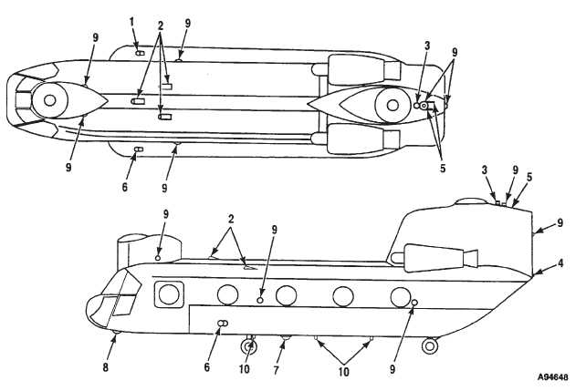
Three position lights (1, 4, and 6, fig. 2-13-1) are installed
on the helicopter. On the right side of the fuselage is a
green light (1); on the left, red (6); and on the vertical
panel of the aft pylon, white (4). Power to operate the
position lights is supplied by the No. 2 DC bus through the
LIGHTING POS circuit breaker on the No. 2 PDP.
2-13-2. Position Light Switches.
a.
POSN Light Switch. The POSN (position)
switches located on the EXT LTG (exterior lighting) panel
on the left side of the overhead switch panel (fig. 2-1-10).
The three position switch is labeled DIM, OFF, and BRT.
It adjusts the intensity of the position lights. When the
switch is OFF, the position light system is deenergized.
NOTE
The crew chief must inform the pilot when the
AFT POS LIGHT switch has been changed to
the OFF position.
b.
AFT POS LIGHT Switch. The AFT POS LIGHT
switch is located in the cabin at sta. 534 near the MAIN-
TENANCE PANEL (fig. 2-13-4). The guarded two-posi-
tion switch is labeled OFF and ON. It allows the aft posi-
tion light to be turned off during aided (NVG) operations
and on during unaided night operations.
2-13-3. Formation Lights.
There are five electroluminescent panels for normal
night formation operations (2 and 5, fig. 2-13-1) and eight
NVG compatible formation lights for NVG formation op-
erations (9, fig. 2-13-1)
Figure 2-13-1. Exterior Lights


