TM 1-1520-240-10
2-12-1
SECTION XII. AUXILIARY POWER UNIT
2-12-1. General.
The gas turbine auxiliary power unit T62-T-2B (APU) (fig.
2-12-2) is mounted in the aft cabin above the ramp. The
basic components of the APU are the gas turbine engine,
hydraulic motor-pump, fuel control, accessory drive, and
AC generator. An APU Electronic Sequencing Unit
(ESU) which monitors APU operation is on the left side
of the cabin above the ramp. the ESU is also labeled APU
CONTROL BOX.
The motor-pump on the APU pressurizes the utility and
hydraulic system for main engine starting and ground
checks. The APU also drives an AC generator which
supplies power to the No. 1 and No. 2 electrical systems.
Refer to Section VI for further information on the hydrau-
lic systems. The APU oil supply is intergal and contained
within the sump of the accessory drive assembly. The
APU receives fuel from the left main fuel tank through a
booster pump, a manual fuel shutoff valve, and a sole-
noid valve.
2-12-2. Electronic Sequencing Unit.
The ESU is mounted on the left side of the cabin above
the ramp. The unit monitors APU starting and operation.
in addition, it monitors APU speed and exhaust gas tem-
perature. the unit continuously compares these parame-
ters with limits programmed into ESU circuits. If a limit is
exceeded, the ESU will automatically shut down the
APU.
NOTE
The BITE indicators indicate engine condition
only. They will not indicate a defective hydrau-
lic motor-pump or generator.
Four magnetic built-in-test-equipment (BITE) indicators
are on the ESU. These indicators are either black or
white. A label on the ESU explains the various BITE
indications and their meaning.
2-12-3. APU Switch.
The APU switch is on the ELEC panel of the overhead
switch panel (fig. 2-11-2). It is a three-position switch
labeled OFF, RUN, and START. The switch is spring
loaded from START to RUN. Normally, power to operate
the APU is supplied by the DC essential bus through the
APU CONT NORM circuit breaker on the No. 1 PDP.
Emergency power to operate the APU is from the battery
bus through the APU CONT EMERG circuit breaker on
the No. 1 PDP.
2-12-4. APU ON Caution.
The APU ON caution capsule is on the mater caution
panel (fig. 2-14-5 and 2-14-6). Normally, the APU is in-
tended for ground operation only. It is not intended for
operation during flight. If the caution remains illuminated
following take-off, it alerts the pilot to shut down the APU.
When the caution is illuminated it indicates the APU is up
to speed and the exhaust gas temperature is normal. It
does not necessarily indicate that APU hydraulic pump
or generator output is normal. If rotors are not turning,
check the UTIL HYD SYS and RECT OFF cautions to
evaluate output of the APU hydraulic pump and genera-
tor. The APU ON caution is controlled by the ESU.
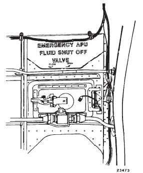
2-12-5. Emergency APU Fluid Shut Off Vavle.
The EMERGENCY APU FLUID SHUT OFF VALVE is in
the fuel supply line to the APU (fig. 2-12-1). It is located
inside the aft cabin above and to the left of the ramp
interphone station. The valve can also be reached from
the outside through an access door labeled ACCESS
APU EMER FLUID SHUT OFF. The knob on the valve
has an OPEN and CLOSE position. Placing the knob to
CLOSE shuts off fuel to the APU.
Figure 2-12-1. Emergency APU Fluid Shut OFF
Valve