TM 1-1520-240-10
2-10-1
SECTION X. HEATING, VENTILATION, COOLING, AND ENVIRONMENTAL
CONTROL SYSTEMS
2-10-1. Heating and Ventilating System.
A 200,000 btu/hr capacity internal combustion heating
system is provided. it consists of a heater unit, a fuel
control unit, an ignition assembly, a blower, control re-
lays, and air pressure and temperature control circuits.
Ducting carries heated air or ventilating air to the cockpit
and the cabin. The heater consumes approximately 15
pounds of fuel per hour from the right main fuel tank.
The heater and blower are mounted vertically on the right
side of the helicopter, immediately aft of the forward cab-
in section bulkhead. Air for the system is provided by the
blower which draws air from an inlet on the forward upper
side of the fuselage. If sufficient air is not available for
proper heater operation, an automatic differential pres-
sure switch in the heater circuit will stop the heater.
Both ventilating and combustion air enters the heater
inlet. The heating air passes over the heated metal walls
of the combustion chamber and is directed to a network
of ducting. The air entering the combustion chamber is
combined with atomized fuel and, after combustion that
heats the metal walls, the exhaust is discharged through
an outlet on the forward upper side of the fuselage. Pow-
er to operate the blower is supplied by the No. 2 AC bus
through the CABIN HEATER BLOWER circuit breaker on
the No. 2 PDP. Power to the rest of the system is supplied
by the No. 2 DC bus through the CABIN HEATER CONT
circuit breaker on the No. 2 PDP.
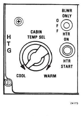
2-10-2. HTG Panel.
The HTG (heating) panel (fig. 2-10-1) is located on the
overhead switch panel (fig. 2-1-10). It consists of a rheo-
stat-type CABIN TEMP SEL rotary switch, a three-posi-
tion heater function switch, and a spring-loaded push-
buttton HTR START switch.
a.
CABIN TEMP SEL Rotary Switch. The CABIN
TEMP SEL rotary switch is labeled COOL and WARM.
This switch operates in conjunction with the temperature
controller relay in the heater circuit and with a cabin ther-
mostat. One set contacts on the temperature controller
relay closes to complete a circuit to the fuel control sole-
noid valve. This allows fuel to be delivered to the heater.
The second set of contacts on the temperature controller
relay closes to complete the circuit to the heater windings
in the cabin thermostat. The heater windings heat a col-
umn of mercury in the thermostat, causing it to rise.
When the mercury column reaches a 34_C contact, the
temperature control relay is shunted, causing its contacts
to open and interrupt the circuit to the fuel control sole-
noid valve. This stops heater operation by shutting off the
fuel supply to the heater.
Figure 2-10-1. HTG Panel
The circuit to the thermostat heater winding is also inter-
rupted, allowing the winding to cool and the mercury
column to contract, thus reenergizing the temperature
controller relay. this creates a cycling effect, the rate of
which can be varied by increasing or decreasing the
resistance between the temperature selector and he
thermostat heating winding. Resistance is varied by turn-
ing the CABIN TEMP SEL rotary switch. this increase or
decrease in resistance directly varies the time the heater
is allowed to operate before being automatically cycled.
b.
Heater Function Switch. The heater function
switch is labeled BLWR ONLY , OFF, and HTR ON. The
switch selects the desired feature of the heating and
ventilating system. When the switch is set to BLWR
ONLY, the blower forces unheated air into both the cock-
pit and cabin. Further movement of the heater controls is
not required. Selecting HTR ON energizes the various
units of the heater once the HTR START switch is pres-
sed. The heating and ventilating system is shut down
when the switch is set to OFF.
c.
HTR START Switch. When HTR ON is selected
on the heater function switch and the HTR START switch
is pressed, the heater control circuits are energized. The