TM 1-1520-240-10
2-14-1
SECTION XIV. FLIGHT INSTRUMENTS
2-14-1. General.
The following paragraphs contain information on the
flight instruments. Information on the navigation instru-
ments will be found in Chapter 3. Avionics. All other in-
struments directly related to one of the helicopter sys-
tems are found under the appropriate system heading in
this chapter. Refer to fig. 2-1-5, 2-1-6, 2-1-7, 2-1-8, 2-1-9,
and 2-1-10 for illustrations of the instrument panels,
canted and center consoles, and overhead switch panel.
2-14-2. Cruise Guide indicator System.
The cruise guide indicator (CGI) system gives the pilot a
visual indication of actual loads imposed on critical com-
ponents of the helicopter dynamic system. The system
allows the pilot to achieve maximum helicopter utilization
under various conditions of payload, altitude, airspeed,
ambient temperature, and center-of-gravity. The system
consists of strain gages bonded to fixed links in the for-
ward and aft rotor controls, an indicator, a signal proces-
sor unit in the aft pylon, a signal conditioner unit in the
forward pylon, and interconnecting wiring. The system
measures alternating stress loads at each rotor and dis-
plays the larger of the two signals. Power to operate the
cruise guide indicator system is supplied by No. 2 DC bus
through the CRUISE GUIDE circuit breaker on the No. 2
PDP.
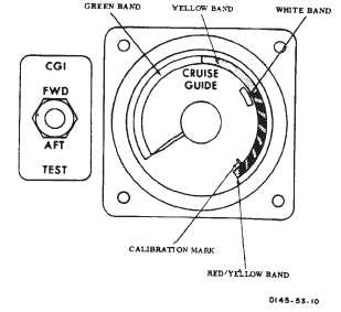
2-14-3. CRUISE GUIDE Indicator.
The CRUISE GUIDE indicator is on the pilot instrument
panel (fig. 2-14-1). Three bands are colored green, yel-
low, and striped red-and-yellow. Refer to figure 5-2-1 for
limitations. Immediate corrective action must be taken to
reduce stress when in the red-and-yellow striped band.
This can be accomplished by lowering THRUST CONT
lever, reducing airspeed, releasing back pressure on the
cyclic stick, or by reducing the severity of the maneuver.
NOTE
Do not test the cruise guide system with rotors
turning. False indications will result.
When the switch is placed from the center position to
each test position, the pointer on the indicator should
indicate within the white test band. The white test band
indicates proper system operation.
When the test function is activated, circuits from the
strain gages to the indicator are tested. However, sepa-
ration of the bond of the strain gage to a link will not be
detected by the test function. The narrow white line to-
wards the high end of the striped red-and-yellow band is
used for calibrating the indicator during bench test.
Figure 2-14-1. Cruise Guide Indicator
2-14-4. CGI TEST Switch.
The CGI TEST switch is on the pilot instrument panel, on
the left side of the indicator (fig. 2-14-1). It is a three-posi-
tion switch spring loaded to center off position labeled
FWD and AFT.
2-14-5. Airspeed Indicator.
There are two airspeed indicators located on the upper
left portion of the copilot and pilot instrument panel (fig.
2-1-7 and 2-1-9). The difference between dynamic pres-
sure and static pressure as measured by the pitot static
system is introduced into these instruments. Indicated
airspeed is shown in knots.
2-14-6. Altimeter.
An AIMS altimeter is provided for the pilot (fig. 2-14-2).
In the term AIMS, the A stands for Air Traffic Control
Radar Beacon System (ATCRBS), the I stands for identi-
fication friend or foe (IFF), the M represents the Mark XII
identification system, and the S means system. A pneu-
matic counter-drum-pointer type altimeter is installed for
the copilot. The pilots altimeter is a pneumatic counter-
drum-pointer type which is a self-contained unit consist-
ing of precision pressure altimeter combined with an alti-
tude encoder.
Simultaneously, the display indicates and the encoder
transmits through the transponder the altitude of the heli-
copter. Altitude is displayed on the altimeter by a
10,000-foot counter, and a 100-foot drum. A single point-
er indicates hundreds of feet on a circular scale with
50-foot center markings. Below 10,000 feet a diagonal