TM 1-1520-240-10
2-13-7
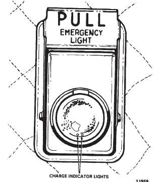
on. The circuit monitors electrical failures and landings in
excess of 3 to 4g’s. The light from the charge indicator
lamps can be seen emitting through two pin holes at the
base of the main light reflector. When the switch is set
from ARM to TEST, the main light comes on, powered by
the batteries. When the switch is set to DISARM, the
indications are the same as for the ARM position, except
the circuit does not monitor electrical or failures hard
landing.
Figure 2-13-3. Emergency Exit Light